Published by Jessica Masters – Latest update on 06/09/2021
ID: TN016
Relevant product(s): L-Edit
Operating systems: Linux RHEL 6 and above / Windows 7 and above
Versions affected: All
Relevant area(s): Technology / Automation
Summary
Standard DRC is the native tool in L-Edit for checking a layout cell for possible issues. With the help of derived layers, a user can configure Standard DRC to define complex rules. This tech note shows how to realise complex rules in Standard DRC using an example.
Details
Standard DRC can execute rules on the design which are based on a pair of derived layers, drawn layers, or a combination of both. This technique takes advantage of this capability derive complex rules.
Step 1: Defining the derived layer(s)
For an example of using Standard DRC, Boolean operations will be used. In this example, two overlapping shapes from different layers need to have a minimum overlapping width with each other. To test this, a new layer will be made. To make the new layer, open the Setup menu and select Layers… Add a new layer using the add button. In this example the layer is called “NewDerivedLayer”. Select the Derivation tab and change it from drawn to derived. Make the Derivation type: Boolean, and select the two layers that will be overlapping. This can all be seen below. Choose any rendering settingsand select OK.
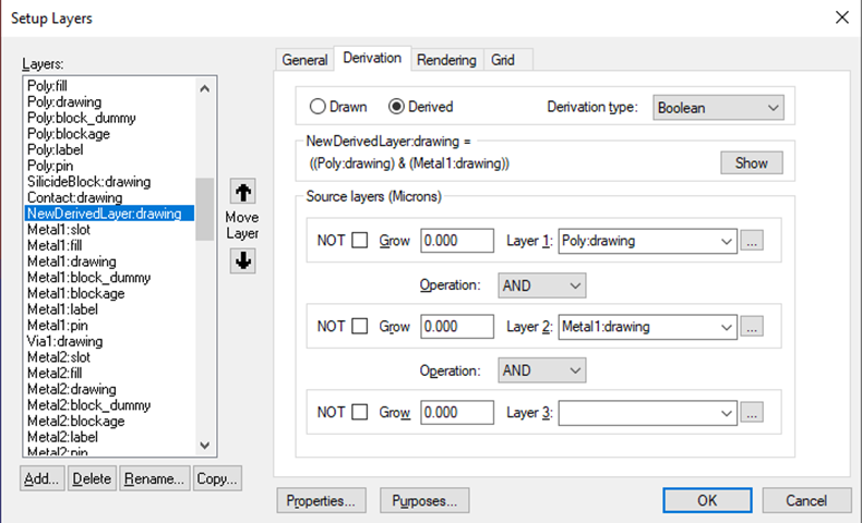
Note that “Derivation type” allows layer relationships of types “Boolean, Select, Area and Density”, please refer to the “References” section to learn more about these relationships and how to make most use of them.
Step 2: Creating the rule(s)
Standard DRC (aka “Tanner DRC”) can be used and configured via the verification toolbar in L-Edit, which can be enabled in the View menu and selecting toolbars. The verification toolbar can be seen below.
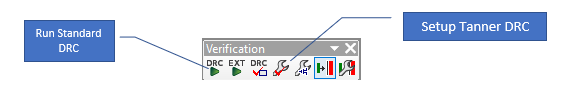
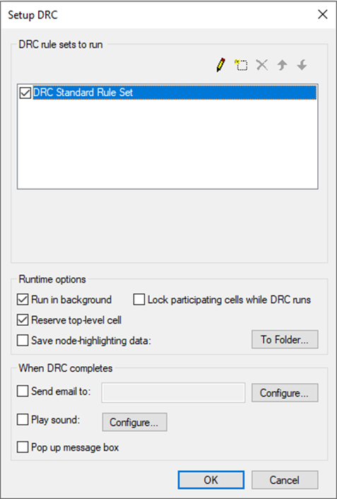
Open the set-up dialog using the “Setup Tanner DRC” icon from the verification toolbar and ensure “DRC Standard Rule Set” is selected, then please press the Pencil icon in the top right corner of the dialog to edit. Also within this dialog, various options can be selected within the setup, such as a message when it has finished running, locking cells while the DRC is running, or running the DRC in the background.
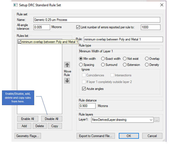
Beneath the Rules List box (shown below), select add to create a new rule. This rule will make sure that the minimum overlap between the two layers is greater than 0.9 Microns. The details for setting this up are shown below. Note that the layer selected for minimum width is the derived layer “NewDerivedLayer” to work out overlap width.
There are a variety of rule types available:
- Minimum Width specifies the minimum width
- Exact Width specifies a set width of an object in all directions
- Not Exist ensures that there are no objects on the specified layer
- Overlap determines how much an object on one layer can overlap with an object on another object if they overlap. This does not include any objects that are entirely surrounded by the other object
- Spacing rules specify the minimum distance between two objects, either on the same layer or two different ones
- Surround ensures that an object on one layer must be fully surrounded by objects on another layer
- Extension rules are similar to Overlap rules, an object must extend out from an object by the minimum distance specified, although if the object is surrounded but shares an edge, it still will be picked up by the rule.
- Density rule ensures that the selected layer is a density type derived layer. It also ensures that there are no polygon outputs on the layer.
Step 3: Run Standard DRC to test
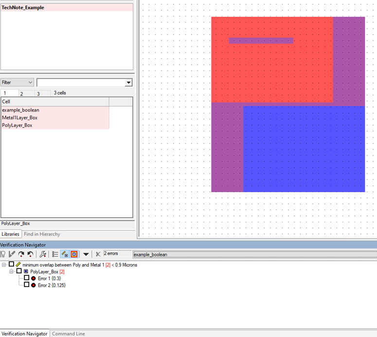
To run Standard DRC, select the “Run Tanner DRC” icon on the Verification toolbar. This will run the rules that have been set up. Below, the example with overlapping layers using NewDerivedLayer. This resulted in 2 errors, 1 occurring when the poly layer surrounds the metal 1 object, and the other when the overlap between the two layers is too narrow. The two layers overlap when it appears as purple. This is shown in the “Verification Navigator” view in L-Edit, which can be enabled from the “View” menu.
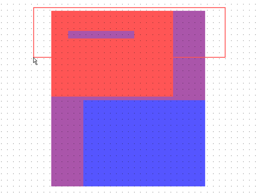
The DRC can also run on a specified area, using the “DRC Box” icon on the Verification toolbar and drawing a box over the area to check, as shown below.
The example file used in this technote can be found below.
Attachments
Example design file for Standard DRC setup: https://we.tl/t-55xr1mltjO