Published by Henry Frankland – Latest update on 04/08/2021
ID: TN012
Relevant product(s): L-Edit
Operating systems: Linux RHEL 6 and above; Windows 10
Versions affected: 2020.3 U 3 and above
Relevant area(s): Automation
Summary
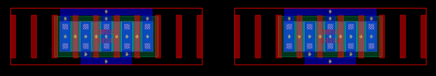
The abutment feature in L-Edit allows users to take MOS devices that may have bracketing dummy poly devices and perform drain/source sharing at a press of a button. This tech note concerns 22nm processes.
Details
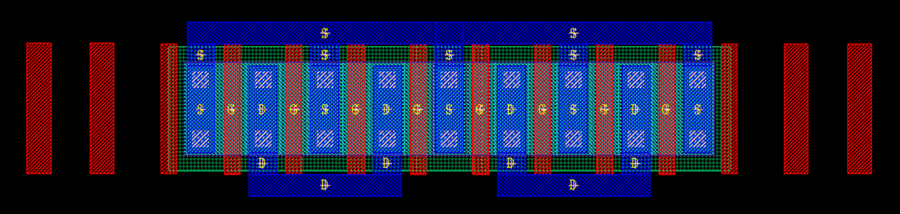
The feature will take two MOS devices that can have poly dummy structures, perform necessary structure trimming in order to have a correctly abutted MOS devices that share a drain or source.
Initial layout before abutment:
Final layout after abutment:
Prerequisites:
- A PDK with enabled abutment features
- SDL netlist from S-edit loaded into L-edit for the instances you want to abut together for drain/source sharing
There are two methods for performing this quick MOS device abutment detailed below.
Method 1 (Auto-abutment):
- Select instance A you want to abut to instance B
- With the cursor over the Drain/Source of instance A that you want to share with instance B, move instance B by holding middle click so that the drain/source of A and B overlap
- Press “Shift + A“ on the keyboard
Method 2 (Manual):
- Select two instance that are to be abutted
- Press “Shift + A” keys to abut
Note:
- In this mode the abutment pick first valid abutment side to perform the abutment
- To change the side which is abutted to the first selected instance will need to be flipped
- you start with M1 M2|M3, instead of getting overlapped M2|M3/M1, by flipping M1 horizontally the structure will be M1|M2|M3
Useful references
Tanner L-Edit User’s Manual – Schematic-Driven Layout (SDL)
Enhance Your Layout Productivity Using Schematic Driven Layout (SDL)